learn more about rapid item location with rfid
RFID based Geiger counting is one of the most common RFID applications on the shop floor. In this article our in-house RFID experts discuss how to create best-in-class practise Geiger counting and why from a more technical point of view.
Most mobile RFID readers carry a software for tag locating. Simply, it means a software for locating individual tags, and the name ‘Geiger counting’ comes from the ticking sound that appears when the RFID reader approaches the searched tag. As the RFID reader gets closer to the searched tag, the ticking sound speeds up.
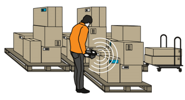
The idea of Geiger counting is to locate a specific tag in a densely packed environment with the help of a handheld device. To be able to do this all relevant items needs to be tagged on item level. Geiger counting would be used for example for searching for a specific shirt in a certain size in a store, or for looking for a missing cardboard box in a warehouse.

THE BASICS OF GEIGER COUNTING
In simple terms Geiger counting means using the RSSI values of tags to determine if they are close or far away from the reader, and indicate this to the user of the RFID device. However, as in any RF environment, the more the transceiver emits RF energy, the higher is the signal strength received from the tag. Therefore, in addition to the RSSI values, good Geiger counting applications should add the output power to the calculation. Next, we will propose how to work with the RSSI values and output power to optimize the results. Finally, we will discuss how to build an application for Geiger counting.
The output power should be taken into consideration so that when the reader receives the “highest” possible RSSI value, it should lower the output power and check if it is still receives the same signal strength. If it does, it shall continue to lower its power until it either reaches the lowest possible setting for the output power, or until the RSSI value starts to decrease. If the RSSI value gets low enough, the application should increase the output power. If the signal strength stays up even with low output power, then it is reasonable to assume that the tag is really close to the reader.
The method mentioned above is the most typical way of performing Geiger counting as a majority of the devices have only one antenna mode. When a device has more than one antenna mode including proximity and circular antenna modes, the additional antennas can determine the proximity of the tag with higher accuracy. When working with such units, the application can monitor the power output and when it is low enough and the RSSI stays at a certain level, the reader can switch to an antenna with a shorter read range.
HOW TO BUILD A GEIGER COUNTING APPLICATION?
1) Perform Inventory with select parameters using the EPC code you wish to locate. Use session 0 since we need the tag to reply to every query.
- Inventory with select parameters allows restricting tag populations to tags that have only a certain bit pattern(s) in their memory at a specified bank and bit address.
- Even if the session-value is adjustable, session 0 is the only option when performing Geiger counting.
a) If the tag is seen after the step above, then acquire the RSSI from the tag and “buffer” it, i.e. calculate an average value of for instance the last 5 received RSSI values.
b) If the tag is not seen, then buffer a scaled RSSI value of 0 to imply that the tag was not seen.
c) Calculate an average value based on the received RSSI
i) If the averaged RSSI is in the “maximum” RSSI range (for example between 70-100%), lower the output power by 1dBm.
ii) If the averaged RSSI is in the “low” RSSI range (for example between 0-40%), raise the output power by 1dBm.
2) While the “Geiger counting”-thread is performing the above, the UI-thread should have a e.g.a timer which ticks every 100ms and updates the Geiger beeping and any other UI related tasks.
a) In addition to the timer, the beeps should also be visible in a separate thread, and let the timer ticks reset an event which tell the “Beeping”-tread to generate the required sounds
i) When such an event is received, the “Beeping”-thread should use the averaged value of the received RSSIs for manipulating the interval and frequency of the beeping.
ii) Then it is more or less a matter of preference which kind of beeping each possible value should generate. E.g. a beep with 1568Hz frequency could be generated when the tag is seen and a 1046Hz when it is not seen. The length and interval of each beep could be defined by the received averaged RSSI value i.e. 100% = beep for 100ms without any interval, anything below 100% = 50ms beep with (250 – averaged rssi value) ms interval.
RFID READERS FOR GEIGER COUNTING
Most of the mobile RFID readers available on the market can be equipped with a tag locating software. In order to maximize accuracy when locating a certain tag, the mobile RFID reader should have as narrow an antenna beam as possible. As most RFID readers on the market are equipped with an omni-directional antenna beam, the application software will need to control the antenna beam.
For more insights on RFID, learn how the user can affect the reading patterns of UHF RFID performance in this article.